Security Alarm With Ldr Circuit Diagram . The laser light security system using 555 timer operates by monitoring the presence of a continuous laser beam. Ldr latch circuit/ security alarm with ldrvideo link: Since the ldr is connected to the base. Let's get started, step 1: At the heart of the circuit is a 555 timer ic, configured in. Take all components as shown below. In the above circuit diagram, we can see that the npn transistor is acting as a switch. Today i am going to make a circuit of security alarm with ldr. This laser security alarm circuit uses two bc548 npn transistors as a switching device. Laser security system circuit diagram. In this tutorial, we are going to demonstrate a circuit of a laser security alarm system that will detect any irregular activity.
from www.robotshapers.com
The laser light security system using 555 timer operates by monitoring the presence of a continuous laser beam. This laser security alarm circuit uses two bc548 npn transistors as a switching device. Ldr latch circuit/ security alarm with ldrvideo link: Today i am going to make a circuit of security alarm with ldr. Since the ldr is connected to the base. Let's get started, step 1: At the heart of the circuit is a 555 timer ic, configured in. In the above circuit diagram, we can see that the npn transistor is acting as a switch. In this tutorial, we are going to demonstrate a circuit of a laser security alarm system that will detect any irregular activity. Take all components as shown below.
LDR Light dependent resistor circuit or light detector circuit using
Security Alarm With Ldr Circuit Diagram Let's get started, step 1: Let's get started, step 1: Ldr latch circuit/ security alarm with ldrvideo link: In the above circuit diagram, we can see that the npn transistor is acting as a switch. In this tutorial, we are going to demonstrate a circuit of a laser security alarm system that will detect any irregular activity. The laser light security system using 555 timer operates by monitoring the presence of a continuous laser beam. Since the ldr is connected to the base. Take all components as shown below. Today i am going to make a circuit of security alarm with ldr. This laser security alarm circuit uses two bc548 npn transistors as a switching device. Laser security system circuit diagram. At the heart of the circuit is a 555 timer ic, configured in.
From www.circuitdiagram.co
ldr schematic diagram Circuit Diagram Security Alarm With Ldr Circuit Diagram Since the ldr is connected to the base. In the above circuit diagram, we can see that the npn transistor is acting as a switch. Today i am going to make a circuit of security alarm with ldr. Let's get started, step 1: Laser security system circuit diagram. Take all components as shown below. At the heart of the circuit. Security Alarm With Ldr Circuit Diagram.
From www.ee-diary.com
Laser Diode & LDR based alarm system using Arduino eediary Security Alarm With Ldr Circuit Diagram In this tutorial, we are going to demonstrate a circuit of a laser security alarm system that will detect any irregular activity. Take all components as shown below. Ldr latch circuit/ security alarm with ldrvideo link: At the heart of the circuit is a 555 timer ic, configured in. This laser security alarm circuit uses two bc548 npn transistors as. Security Alarm With Ldr Circuit Diagram.
From schematicsestet.z13.web.core.windows.net
Circuit Diagram Of Ldr Security Alarm With Ldr Circuit Diagram The laser light security system using 555 timer operates by monitoring the presence of a continuous laser beam. In the above circuit diagram, we can see that the npn transistor is acting as a switch. Laser security system circuit diagram. This laser security alarm circuit uses two bc548 npn transistors as a switching device. In this tutorial, we are going. Security Alarm With Ldr Circuit Diagram.
From www.circuitdiagram.co
Circuit Diagram Of Laser Burglar Alarm Circuit Diagram Security Alarm With Ldr Circuit Diagram Take all components as shown below. Ldr latch circuit/ security alarm with ldrvideo link: Since the ldr is connected to the base. In this tutorial, we are going to demonstrate a circuit of a laser security alarm system that will detect any irregular activity. The laser light security system using 555 timer operates by monitoring the presence of a continuous. Security Alarm With Ldr Circuit Diagram.
From freakengineer.com
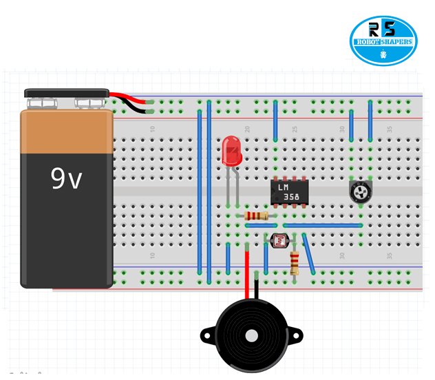
9v ldr circuit mini project for ece » Freak Engineer Security Alarm With Ldr Circuit Diagram In this tutorial, we are going to demonstrate a circuit of a laser security alarm system that will detect any irregular activity. Take all components as shown below. Since the ldr is connected to the base. Ldr latch circuit/ security alarm with ldrvideo link: Laser security system circuit diagram. At the heart of the circuit is a 555 timer ic,. Security Alarm With Ldr Circuit Diagram.
From www.youtube.com
How to Make Security Alarm With LDR YouTube Security Alarm With Ldr Circuit Diagram In the above circuit diagram, we can see that the npn transistor is acting as a switch. Today i am going to make a circuit of security alarm with ldr. Take all components as shown below. This laser security alarm circuit uses two bc548 npn transistors as a switching device. Let's get started, step 1: Since the ldr is connected. Security Alarm With Ldr Circuit Diagram.
From www.youtube.com
How to make Night Security Light Control Automatic Movement Detection Security Alarm With Ldr Circuit Diagram Since the ldr is connected to the base. In the above circuit diagram, we can see that the npn transistor is acting as a switch. Take all components as shown below. Ldr latch circuit/ security alarm with ldrvideo link: In this tutorial, we are going to demonstrate a circuit of a laser security alarm system that will detect any irregular. Security Alarm With Ldr Circuit Diagram.
From www.circuitdiagram.co
Circuit Diagram Of Burglar Alarm Using Ldr Circuit Diagram Security Alarm With Ldr Circuit Diagram Let's get started, step 1: This laser security alarm circuit uses two bc548 npn transistors as a switching device. Take all components as shown below. Since the ldr is connected to the base. In this tutorial, we are going to demonstrate a circuit of a laser security alarm system that will detect any irregular activity. In the above circuit diagram,. Security Alarm With Ldr Circuit Diagram.
From diagrampartsankt.z13.web.core.windows.net
Car Burglar Alarm Circuit Diagram Security Alarm With Ldr Circuit Diagram Ldr latch circuit/ security alarm with ldrvideo link: Since the ldr is connected to the base. The laser light security system using 555 timer operates by monitoring the presence of a continuous laser beam. Let's get started, step 1: Take all components as shown below. This laser security alarm circuit uses two bc548 npn transistors as a switching device. At. Security Alarm With Ldr Circuit Diagram.
From diagramlibrarypern.z21.web.core.windows.net
Circuit Diagram Of Ldr Sensors Security Alarm With Ldr Circuit Diagram In the above circuit diagram, we can see that the npn transistor is acting as a switch. In this tutorial, we are going to demonstrate a circuit of a laser security alarm system that will detect any irregular activity. Laser security system circuit diagram. This laser security alarm circuit uses two bc548 npn transistors as a switching device. Let's get. Security Alarm With Ldr Circuit Diagram.
From www.academia.edu
(DOC) LASER BASED SECURITY ALARM (Using LDR) (Circuit Schematics Theory Security Alarm With Ldr Circuit Diagram In the above circuit diagram, we can see that the npn transistor is acting as a switch. This laser security alarm circuit uses two bc548 npn transistors as a switching device. Let's get started, step 1: Since the ldr is connected to the base. Ldr latch circuit/ security alarm with ldrvideo link: Take all components as shown below. The laser. Security Alarm With Ldr Circuit Diagram.
From www.circuits-diy.com
Laser Security Alarm Circuit using LDR Security Alarm With Ldr Circuit Diagram At the heart of the circuit is a 555 timer ic, configured in. Let's get started, step 1: Laser security system circuit diagram. In the above circuit diagram, we can see that the npn transistor is acting as a switch. Take all components as shown below. Ldr latch circuit/ security alarm with ldrvideo link: In this tutorial, we are going. Security Alarm With Ldr Circuit Diagram.
From www.circuits-diy.com
Simple Laser Security Alarm Using LDR Security Alarm With Ldr Circuit Diagram Laser security system circuit diagram. This laser security alarm circuit uses two bc548 npn transistors as a switching device. The laser light security system using 555 timer operates by monitoring the presence of a continuous laser beam. Ldr latch circuit/ security alarm with ldrvideo link: Let's get started, step 1: In the above circuit diagram, we can see that the. Security Alarm With Ldr Circuit Diagram.
From www.amazon.in
SRROBOTICS Laser Alarm Circuit, Ldr Based Security System (Multi Color Security Alarm With Ldr Circuit Diagram In this tutorial, we are going to demonstrate a circuit of a laser security alarm system that will detect any irregular activity. Let's get started, step 1: Laser security system circuit diagram. This laser security alarm circuit uses two bc548 npn transistors as a switching device. Today i am going to make a circuit of security alarm with ldr. The. Security Alarm With Ldr Circuit Diagram.
From wireenginepaul.z19.web.core.windows.net
Circuit Diagram Of Security Alarm System Security Alarm With Ldr Circuit Diagram Today i am going to make a circuit of security alarm with ldr. In the above circuit diagram, we can see that the npn transistor is acting as a switch. Since the ldr is connected to the base. Ldr latch circuit/ security alarm with ldrvideo link: The laser light security system using 555 timer operates by monitoring the presence of. Security Alarm With Ldr Circuit Diagram.
From devaprojects.blogspot.com
LASER LIGHT SECURITY ALARM..... Security Alarm With Ldr Circuit Diagram Take all components as shown below. Let's get started, step 1: This laser security alarm circuit uses two bc548 npn transistors as a switching device. Laser security system circuit diagram. Today i am going to make a circuit of security alarm with ldr. Ldr latch circuit/ security alarm with ldrvideo link: Since the ldr is connected to the base. In. Security Alarm With Ldr Circuit Diagram.
From userwiringundivulged.z13.web.core.windows.net
Security Alarm With Ldr Circuit Diagram Security Alarm With Ldr Circuit Diagram Take all components as shown below. This laser security alarm circuit uses two bc548 npn transistors as a switching device. At the heart of the circuit is a 555 timer ic, configured in. In the above circuit diagram, we can see that the npn transistor is acting as a switch. Laser security system circuit diagram. The laser light security system. Security Alarm With Ldr Circuit Diagram.
From www.youtube.com
LDR circuit how to make a ldr security circuit YouTube Security Alarm With Ldr Circuit Diagram Laser security system circuit diagram. This laser security alarm circuit uses two bc548 npn transistors as a switching device. Since the ldr is connected to the base. Let's get started, step 1: Take all components as shown below. In the above circuit diagram, we can see that the npn transistor is acting as a switch. Ldr latch circuit/ security alarm. Security Alarm With Ldr Circuit Diagram.